

H2: Introduction
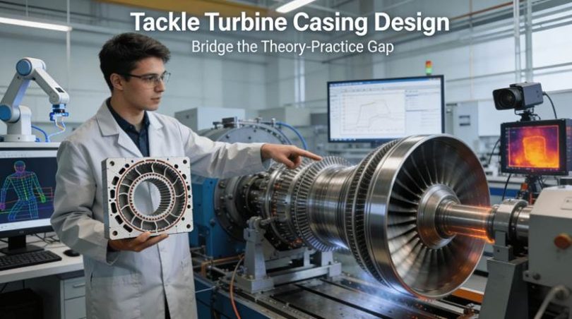
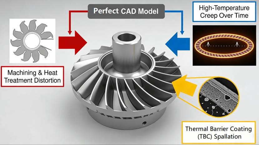
When turbine engines are taught in engineering classes and textbooks, they always appear to be very theoretical and highly idealized. The problem arises, however, when an engineer or a student faces his/her very first real world turbine casing design challenge: the idealized and perfectly sealed geometry of CAD can cause severe engine efficiency drop or even failure during bench tests because of the various problems arising such as machining thermal distortion, vibration of thin walls, or thermal barrier coating spallation.
The reason for such a discrepancy lies in the nature of the engineering education in that different aspects of mechanical design such as design, materials, and manufacturing, are usually taught separately, missing out an integrative view at the effects of their interconnection in extreme thermo-mechanical-chemical conditions. One might have an idea of the material parameters yet not know how the machining stresses affect the creep process of the material at high temperatures. The aerodynamic behavior is well understood; however, the combined tolerance of hundreds of film cooling holes becomes responsible for total cooling effectiveness.
H2: What Factors Might Result in an “Unmanufacturable” Casing Despite Having a “Perfect” CAD Model?
The first and most significant disconnect arises when transitioning from design to production. The perfectly designed CAD model, designed solely for maximum aerodynamic performance, may have internal geometry that is impossible to cut without creating undesirable vibrations. Moreover, ignoring the tendency of high-grade metal alloys to distort during heat treatment and subsequent machining will result in an incorrectly assembled component. Hence, mastering Design for Manufacturability is a prerequisite of concurrent engineering. The knowledge of manufacturing limitations should be acquired through experience with practical methods and solutions, such as through learning how to produce aerospace turbine casing CNC machining. The guide on this topic outlines all the key factors that need consideration: from geometrical design to process choice to distortion compensation. Creating a proper connection between design and manufacturing processes requires, however, an additional analytical foundation. As discussed in MIT OpenCourseWare lessons on product design, modeling geometrical features’ relations with materials and manufacturing is key to engineering decision-making.
l The Ideal of Aerodynamics Versus the Challenges of Manufacturing: The ideal shape of aerodynamics is characterized by seamless continuity. While a streamlined shape may have an aspect ratio greater than ten, which would not allow an ordinary end mill to work effectively inside, machining such a shape would require the use of a very long, thin tool that would bend easily, leaving behind a rough surface with inaccurate dimensions. An ideally shaped surface in simulation can quickly become the cause of vibration, excessive tool wear, and possible material failure when it is actually put into manufacturing.
l The Hidden War: Stresses and Heat Treatment: Stress exists in a raw casing before any machining process takes place. Once the rough machining process strips away a lot of material from the blank, the stresses stored internally within the part will re-balance and deform the part. Further machining processes, such as heat treatment of the Inconel material, relieve the remaining stress while introducing new stress from the uneven heating and cooling process. Without proper knowledge of the hidden stress cycle, the final product will become warped unpredictably.
l Assembly Interfaces and Cumulative Tolerance Risks: The casing is not used alone; it connects to manifold parts, mountings, and many other parts of the engine. One may require a tight tolerance for individual features, but the designer may ignore the cumulative effect when the individual features work together. The total deviation from the correct position of many bolt holes in a big flange will determine the possibility of assembly. In this case, without taking into consideration the cumulative effect in the machining process plan, the assembly will not be possible by any means except force application.
H2: What Makes the Fight Against “Heat” the Key Element in Casing Manufacturing?
The main adversary, or antagonist, in the development of casings for turbines is heat, which leads to many problems associated with various aspects. To begin with, superalloys with high temperature resistance are hard to cut. In terms of operations, these casings have to cope with temperatures that lead to creep and affect clearance between blades. Spallation cracks spread under heat swings. That’s a hidden threat for shields. Engineers track it through metal science, stress models, and surface changes. It starts with a thorough study of micro-level processes and phase transformations taking place in high-temperature materials. Reliable information about superalloys’ behavior at high temperatures can be found in metallurgists’ manuals issued by ASM International.
H3: 1. The Superalloy Dilemma: Strength and Machinability
Machining Inconel 718 wears tools fast. Its gamma-prime phase resists creep at 700C. But it builds hardness when cut. The material scratches easily during shaping. The process should be carefully designed since using incorrect settings can cause the metal surface to work-harden, making subsequent cuts increasingly difficult and heating up the part beyond repair through damage to its metallurgy. Specialized geometry tools, high-pressure coolants, and techniques to handle elevated cutting temperatures are critical – this is where precision CNC machining becomes vital.
H3: 2. Creep: The Insidious, Slow Process That Affects Efficiency
Creep refers to slow and permanent deformation under constant stress due to a high temperature. For the casing, it means that both pressure and temperature differences within the structure generate an applied load, which results in slow deformation after thousands of flight hours. The casing tends to ovalize, causing reduced running clearance between the casing and rotating blade tips. This affects aerodynamic efficiency and may lead to blade rub if the reduction is significant enough. Dealing with the creep issue involves selecting appropriate alloys and controlling their microstructure.
H3: 3. The Fragile Shield: Combining the Ceramic Thermal Barrier Coatings
The ceramic layer acts like a shield, blocking heat from reaching the metal by hundreds of degrees. Thing is, how well it works hinges on the bond at where it meets the metal. Since ceramic and metal expand at different rates when heated, they pull apart over time, Mainly during engine starts and stops. That crackle creates gaps, letting layers flake off. Surface prep matters: you gotta get that roughness right and clean every bit of dust or oil before applying the coating.
H2: Is It Possible to Machine a Large Thin-Walled Part Without Distortion, Like a Potato Chip?
During machining, a large, thin-walled case wants to distort to some degree because of the lack of stabilizing internal material. And the main difficulties arise due to elastic stress distribution and thermal deformations generated during machining. If not controlled actively, the dimensional deviations of the final component can be excessive. Therefore, successful machining of aerospace casings demands careful planning and precise simulations and corrections.
H3: 1. Machining: The Art of Symmetric Material Removal
The art lies in material removal which should keep stress symmetrical. Simply cutting a large pocket makes an asymmetric condition for stress, thus causing warping. Sophisticated methods of machining involve multistep symmetric operations, rough milling, for example, on both sides equally leaving uniform allowance of material, possibly combined with heating to relieve stress. Then semi-finishing operations make the stress distribution symmetrical again, leading to finishing cuts. Such delicate process helps the part reach equilibrium position gradually and predictably.
H3: 2. Predictive Engineering: Distortion of the Toolpath Before Cutting
The Finite Element Analysis predicts the distortion that the part will incur due to deformation following cutting and when the part is no longer clamped. The prediction is fed back to the CNC programming and the part is programmed to be machined such that the toolpath itself is distorted prior to machining. In other words, the toolpath follows a distorted version of the CAD file of the part. After machining, the part pops back into its correct geometry.
H3: 3. Taming the Thermal Beast: Cutting Tool Heat Control
Another significant source of thermal expansion in localized areas is the heat produced by the cutting tool. High-pressure coolant is applied directly to the cutting edge to eliminate the heat generated immediately. In addition, parameters such as high cutting speed with low depth of cut could actually result in generating less heat compared to low-speed heavy cutting processes. Utilizing temperature-controlled machines and process monitoring guarantees that heat does not become a dominating factor influencing geometrical errors.
H2: How Do They Integrate Coatings With Hundreds of Cooling Holes With Micron Precision?
Modern turbines rely on drills to punch exact holes into cases. These go deep inside blades too, helping move hot air away. So the holes must line up perfectly and stay sharp so cooling flows properly. Metal gets coated after drilling, so timing counts. A tiny misalignment ruins everything – even millimeter errors shift performance dramatically.
H3: 1. Drilling For Life: The Importance of Film Cooling Hole Geometry
Film cooling holes act as a lifeline. Each hole needs to be drilled at a certain compound angle through the casing wall, creating a barrier of cool air. The positioning, diameter, and geometry of these holes will determine the flow factor and the effectiveness of the cooling. The film cooling holes can be manufactured by laser drilling or electrical discharge machining, both having micron positioning capability and burr-free edges. It is the effectiveness of all these holes that decides the life span of the casing.
H3: 2. Creating the Ideal Surface: Surface Preparation for Bond Coatings
Blasting the metal surface creates a solid foundation for bond coatings. A clean, textured layer ensures better grip and stronger attachment. Laser texturing adds precision without damaging the base material. Proper chemistry is key – this isn’t just about roughness, it’s about matching molecular interactions. Surface prep handles both physical and chemical demands. Without it, adhesion fails completely. More than half of total bond strength comes from how thoroughly we prepare the surface.
H3: 3. The Integrated Process Chain and Its Digital Thread
However, coordinating and controlling these operations is where the real difficulty lies. Drilling holes after coating will break down the TBC. Thus, a controlled process chain is utilized: machining of the substrate > drilling holes > preparation of the surface > coatings application. In addition, each operation is done following specific parameters, and the product is digitally threaded from the design file through the machine program and then inspection report for each operation.
H2: From Classroom to Flightline: A Case Study in Systemic Thermo-Mechanical Problem Solving
A non-disclosive case study demonstrates the integration of these cross-disciplinary issues exceptionally well. An active clearance control system developed for a titanium intermediate casing for a commercial aircraft engine had failed during a test cycle. Assembly bolt-up stresses coupled with operational thermal loading of the coated structure had caused debonding of the coatings applied by thermal spray, making the sensing mechanism inoperable.
H3: 1. The Multi-Disciplinary Failure
From this investigation, there is clear evidence that the failure was systemic. In the analysis of the bolted assembly using FEA, it was found that the flange distorts from the applied preload, a deformation not anticipated in the machining process. In addition, the coating process introduces heat stress on the coating/substrate system, increasing residual stress. This could not be sustained by the coating/substrate system due to thermo-mechanical fatigue. This is a failure of the engineering design-manufacturing-assembling approach.
H3: 2. The Engineering Solution: Simulation, Compensation, and Process Improvement
The solution to this problem took three forms. Firstly, simulation of the bolted joint using FEA was carried out to determine the amount of distortion of the flange. Secondly, the coating method was modified to use high-velocity oxygen fuel spray coating, which yields denser coatings with reduced thermal loading. Thirdly, process verification tests, such as witness coupon evaluation of every batch of coating, were done.
H3: 3. Outcome: Completing the Feedback Loop From Defects to Certification for Reliability
The newly-designed casings proved their worth through engine testing as the clearance control system worked perfectly. The project demonstrated the effectiveness of the “simulate, compensate and validate” closed-loop process. This example clearly demonstrates that theoretical knowledge needs to come together to develop a viable custom turbine casing solution for use on aircraft. Hence, in order to make complicated designs work as flight-reliable casings, cooperation is needed with a vendor having systemized engineering know-how. For example, the supplier, who specializes in custom precision CNC machining parts, utilizes the full range of capabilities including simulation-driven machining and special processes certification.
H2: How To Validate A Turbine Casing For “Service Performance”, NOT “Drawing Conformance”!
The key point changes from developing a part according to a static cold drawing specification to providing a component certified for working in the harsh and dynamic engine environment thousands of cycles long. This entails changing the approach from inspection based on tolerance check to validation as per proof of fitness-for-purpose. Validation implies the use of tests simulating the actual engine conditions to produce data for validating digital twin and closing feedback loops.
H3: 1. Past the CMM: Environmental Testing and Durability
Following dimensional inspection, the next step is rigorous validation testing. In thermal cycling testing, the part will be repeatedly heated and cooled to simulate starting and stopping of the engine to verify whether any coating spalling or cracking occurs. Creep and stress-rupture testing will be carried out on material samples to validate long-term deformations and lifecycles. Lastly, vibration and modal analysis will confirm that the natural frequencies of the casing are well-separated from engine excitation frequencies to prevent resonance.
H3: 2. Non-Destructive Evaluation: Viewing the Invisible
Validating also includes taking a look at the unseen parts of the material. The surface defects and subsurface defects can be detected using Fluorescent Penetrant Inspection and Ultrasonic Testing respectively. Internal details can also be verified using Industrial CT scanning, where a three-dimensional reconstruction of the internal details is made, which is particularly useful in cases of very complex structures.
H3: 3. Constructing the Digital Twin and Completing the Feedback Loop
All data gained from validation exercises will be fed back into the digital twin, which is a very high-quality simulation model of the part under consideration. If deformation of the part is discovered during validation tests to exceed what was expected, the material model in the finite element analysis is adjusted accordingly. The improved digital twin will then guide the design iteration process and help compensate for manufacturing processes. A cycle of improvement will thus be achieved.
H2: Conclusion
Manufacturing of a turbine casing exemplifies the art of systems engineering since the manufacturing process must seamlessly combine multiple areas of knowledge such as material science, structural mechanics, heat transfer, and ultra-precision machining. In order to successfully produce a turbine casing, one cannot rely simply on having a 5-axis machine; one must have an understanding of the multi-physics effects from the “cold” state on the machine tool to the “hot” state in flight. Students and future engineers, by tackling systems problems of geometric stability, thermal control, and dynamic responses, are able to learn how to close the feedback loop between idealized theory and practical engineering applications.
H2: FAQs
Q: What materials are typically used in turbine housing cases for aerospace engines, and what makes them suitable?
A: Inconel 718 handles extreme heat above 650C without deforming. It resists creep under pressure. Ti-6Al-4V works in cooler zones thanks to light weight and solid strength. These alloys win where stress and temperature collide.
Q: How do you determine the dimensional accuracy of such an elaborate piece?
A: Dimensional measurement involves a hierarchical process. A Coordinate Measuring Machine measures the key parameters and tolerance limits by comparing them to the CAD model. For complex surfaces, 3D laser scanning provides a point cloud for comparison. Functional gauges might also be designed to provide quick measurements during assembly.
Q: What does “creep” mean and what makes it such a serious problem for turbine casings?
A: Creep means the irreversible and time-dependent deformation of materials under constant loads at elevated temperatures. In terms of casings, creep involves gradual sagging after many hours of operation, resulting in loss of blade tip clearance and ultimately decreasing efficiency and leading to blade rubbing. To prevent this phenomenon, special alloy steels and heat treatments, as well as certain design compensations, are used.
Q: Could you elaborate on the meaning of hundreds of tiny holes located on some turbine casings?
A: The holes referred to are film-cooling holes designed to provide air injection into the area between the hot gas flow and metal casing walls. This ensures higher working temperatures, which improve efficiency. The number, shape, and size of these holes are very carefully selected and calculated by engineers.
Q: What is meant by “thermal barrier coating” and how is it applied?
A: Thermal Barrier Coating means a ceramic layer that shields metal from high heat and cuts temperatures down by hundreds of degrees. It’s made by plasma spray or EB-PVD on top of a metal bond coat. Surface prep matters – clean, smooth surfaces help. Thing is, mismatched expansion can cause cracks and flaking if not handled right. Proper technique and clean substrates stop damage from spreading.
H3: Author Bio
The author is a senior manufacturing engineering specialist with more than 15 years of experience working with high integrity aerospace parts through developing practical solutions derived from complex thermo-mechanical theory. They work with LS Manufacturing, an organization specializing in manufacturing services based on rigorous certification. Their capabilities span multi-disciplinary engineering problems involving extreme environment technology applications. Contact their experts for educational institutions and research organizations interested in case studies or technical white papers on component manufacturing technologies.